Accessing the Knowledge Center effectively requires a simple, one-time registration.
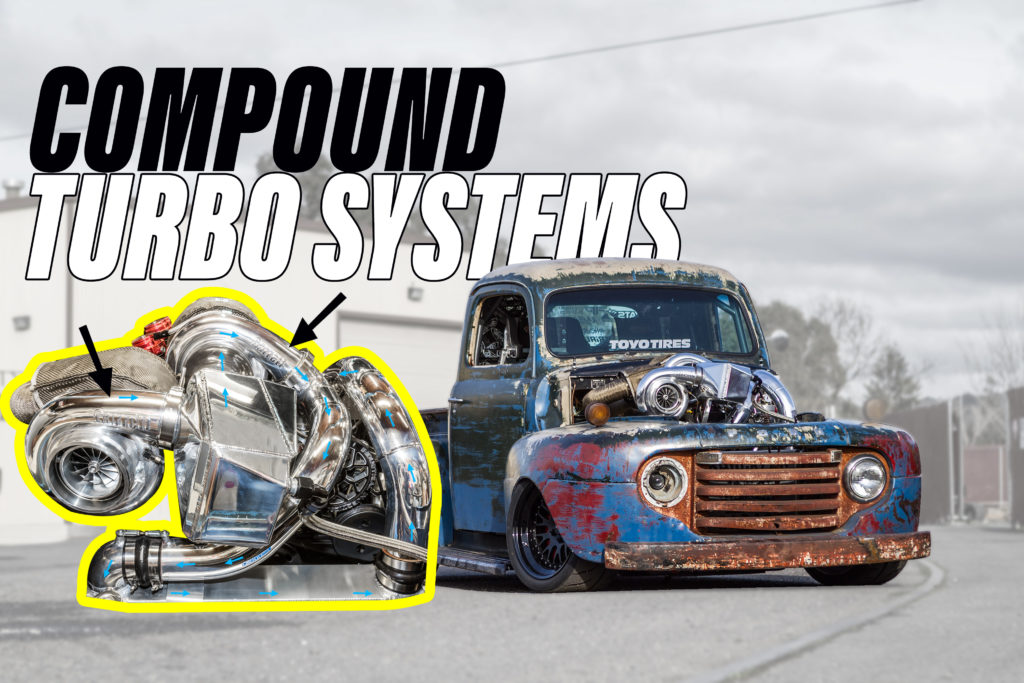
To the untrained eye, a compound turbo setup looks a lot like a twin turbo setup on a car. But, once you trace the piping from the intake and exhaust manifolds to the turbos you begin to identify the major differences between the two. In compound turbo systems, the turbochargers are different sizes and operate in series, meaning the first turbo feeds the second turbo boosted air and the effect is compounded whereas a twin turbo configuration, identical sized turbos operate independently. Compound turbo systems are most common in OEM diesel applications to provide vehicle owners with response, power, and fuel economy. This is accomplished by a small turbo providing low RPM response with a larger turbo producing power at high RPMs and simultaneously the two turbos operate as one throughout the RPM range.
Charge Flow Path
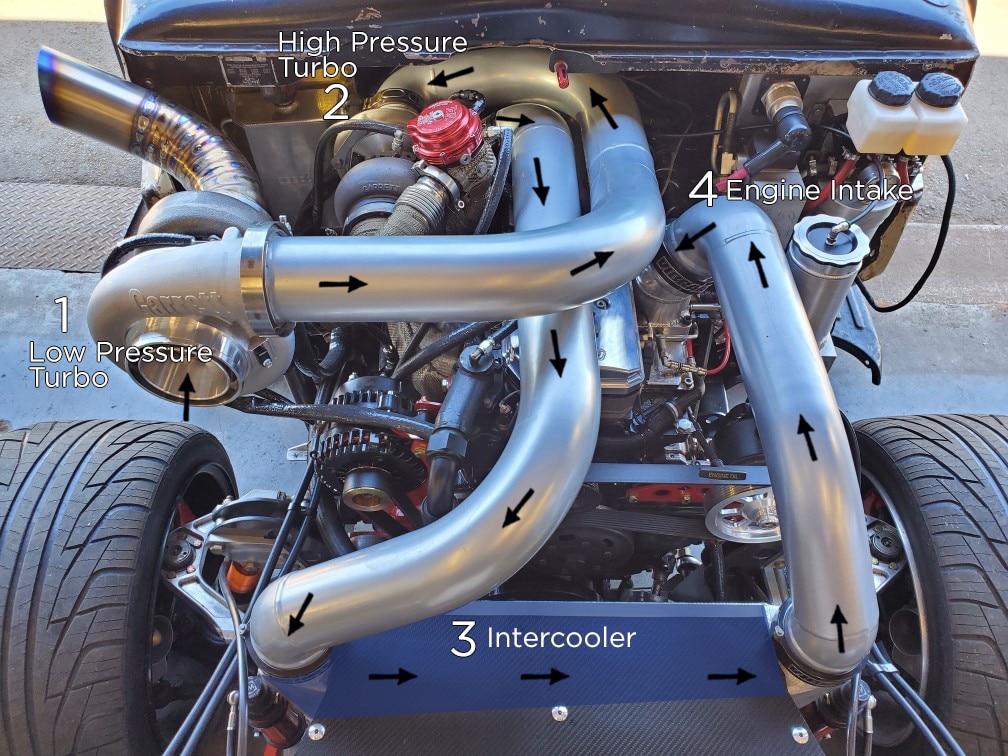
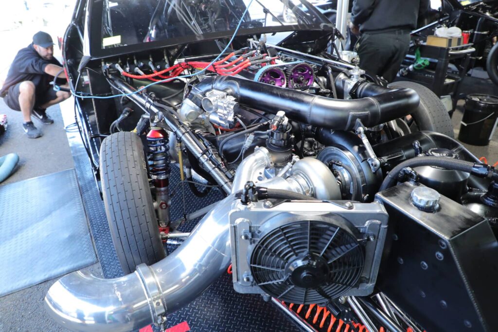
The charge air flow path highlighted in the image shows the air entering the low-pressure turbo first. At low engine RPMs, the low-pressure turbo does not spin very fast and is producing little to no boost, but the air still flows through it into the second/ high-pressure turbo. At low engine RPMs, the smaller, high-pressure turbo produces the initial boost for the engine. As engine RPMs rise, the larger low-pressure turbo spins faster and creates boost which is fed into the high-pressure turbo to be compressed a second time, compounding the boost pressure that the turbos make. After the air leaves the high pressure turbo it is routed through an intercooler to reduce its temperature before going into the engine intake.
Exhaust Flow Path
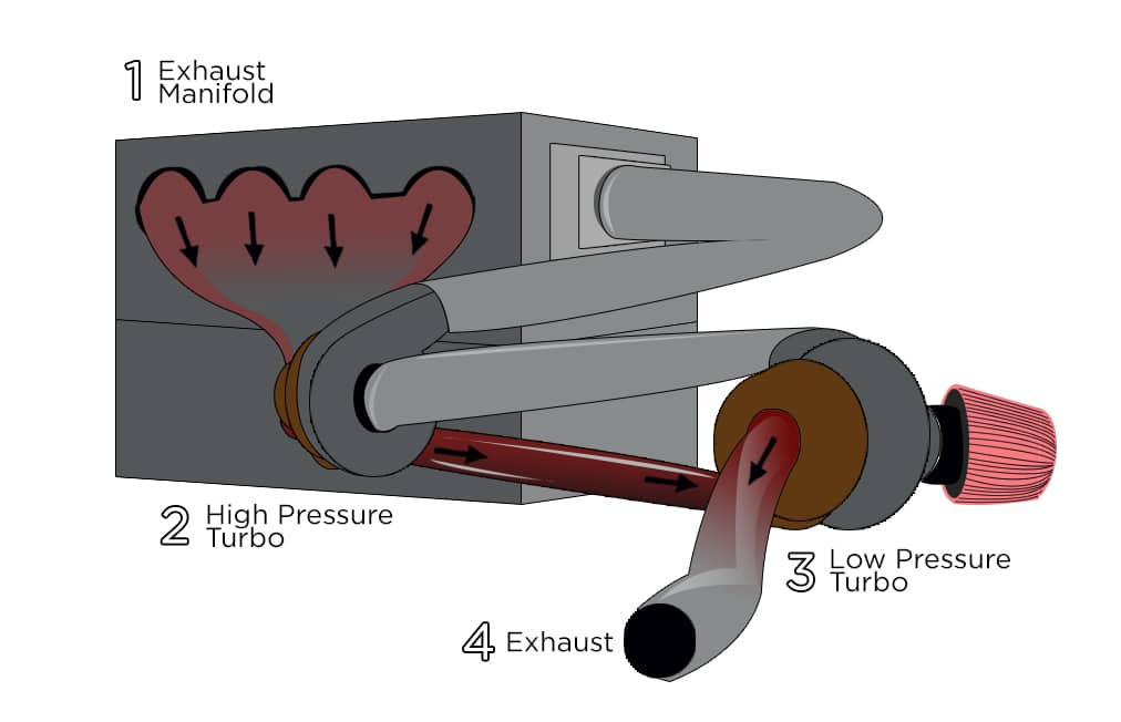
The exhaust flow piping is opposite of the charge air path with the high-pressure turbo connected to the exhaust manifold and the larger/ low-pressure turbo downstream of the flow, with the exhaust gasses leaving the system through the exhaust. One or two wastegates are typically used to control turbo shaft speed allowing the turbos to operate in their desired efficiency zones. The wastegated gasses from the high-pressure turbo are diverted back into the header pipe to be used or wastegated again depending on the shaft speed of the low-pressure turbo.
In the examples below, we will show you two different compound turbo configurations used in racing applications.
Jett Racing – Australia
Collin Wilshire with Jett Racing in Australia has worked years on mastering the science behind compound setups for his race car which is the world’s fastest 4-cylinder compound turbo car with a 6.2 second ¼ mile at 229 MPH. This Mitsubishi Eclipse has a 2.2L 4G63 engine with a compound turbo setup using two Garrett turbochargers and makes about 1900 horsepower. Follow Jett Racing on social media.
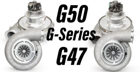
The desire to squeeze more boost from a turbo system would have taken a single turbo out of its efficiency zone and turned it into a heat pump. A compound turbo system makes big boost and keeps both turbos in an efficient zone on the compressor map eliminating the use of intercoolers in this setup. Remember, efficient air is cooler air. The high-pressure turbo is a GTX4202R and the low-pressure turbo is a GTX5533R Gen II. Collin says keeping the turbos operating at a lower RPM provides better boost ratios, cooler intake temps, better clutch control and still produces up to 100 lbs of boost to the engine and close to 1900 horsepower.
Scott Birdsall – Chuckles Garage Old Smokey F1
Old Smokey is a diesel powered race truck with a compound turbo system that was built for racing Pikes Peak, track days, and having fun at Hoonigans Donut Garage. See video below. In diesel truck applications a compound turbo system is necessary for low end response so the high-pressure turbo on this build is a GTW3884R and the low-pressure turbo is a G42-1450. In this configuration, the turbos are operating outside of the max efficiency range which produces higher intake temperatures and therefore needs an intercooler to lower intake temps.
Old Smokey has seen many varieties of turbochargers on his truck including a dual stage intercooler setup between each turbo to cool the temperatures. You can see a full build breakdown in the video below.
Pressure Ratios (PR= P2c/P1c)
Calculating pressure ratios for compound turbo systems can be achieved with the formulas below. This is important for understanding compressor efficiency and potential power for your selected turbochargers. Pressure ratio is a variable equation that combines ambient pressure with gauge pressure divided by ambient pressure. This identifies where the compressor will perform its max duty cycle. Knowing pressure ratio is a key component to selecting the correct turbo for your application. PR is identified on the Y (vertical) axis of the compressor map. Additionally, pressure ratio is not an indicator of horsepower.
P2c Absolute outlet pressure
P1c Absolute inlet pressure
- P2c= (PSIg + PSIa) Boost Gauge Pressure (PSIg) + Absolute Atmospheric Pressure (PSIa)
- P1c = (PSIa) Absolute Atmospheric Pressure (PSIa)
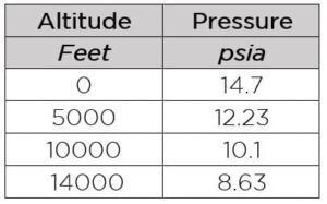
PSIg refers to gauge pressure and measures the pressure above atmospheric. A boost gauge pressure reading of 12 means the pressure in the manifold is 12 psi above atmospheric pressure. Depending on the build of the engine, your gauge pressure limits will vary. Stock engines usually have lower ability to handle boost, while highly modified engines can handle much more. Having a boost target is necessary for determining pressure ratio. PSIa refers to absolute atmospheric pressure. This is standard atmospheric pressure at standard conditions. If you are not at sea level you can substitute a value from the chart below for PSIa.
LP turbo pressure ratio= (ambient + gauge boost / ambient)
HP turbo pressure ratio= (ambient + gauge boost / HP inlet (LP outlet) + ambient)
For more on calculating pressure ratio and selecting the correct turbo please read our How To Select A Turbo Articles: Part 1 and Part 2
