


Performance Upgrade
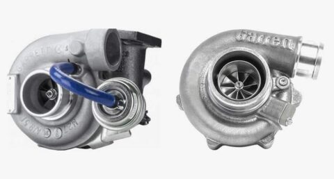
Choosing The Right Turbo
Boost adviser is a program that is designed to help you select a turbocharger that meets your horsepower and engine requirements. Enter the requested inputs and let Boost Adviser find turbo matches for you. This new feature also maps points on different compressor maps of the matched turbos.
Boost Adviser
Garrett Boost Adviser is a tool developed to perform a turbo match quickly and easily. Enter a few parameters for your engine and your horsepower goal and in a matter of seconds, the Garrett Boost Adviser will provide you with the turbochargers that closely meet your inputs. It also guides you to the nearest distributors available to buy a turbo.
Turbo Tech
Turbocharging any engine can be a difficult process to get right the first time. We have broken the main topics into 3 categories: Basic, Advanced, and Expert.
Basic: How a turbo works, components of a turbo, bearing systems, wastegates and blow off valves.
Advanced: Turbo terms like trim, A/R, manifold selection, rich vs lean and compression ratio
Expert: Learn how to read a compressor map, calculate horsepower based on engine displacement, plot points on a compressor map to identify a turbo match
System Optimization
Turbo System Optimization covers the auxiliary systems and how to properly calculate, install, identify problems, as well as tips for how to correct common problems that arise from incorrect installation. You will learn about water lines, siphoning effect, charge air tubing, oil supply, and drainage, oil restrictors and recommended oil pressure. In the end, you will be equipped to understand how to optimize your turbocharger system.
Water Cooling
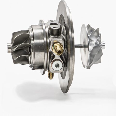
Water-cooling improves mechanical durability and lengthens the turbocharger’s life. Garrett GTX and G Series ball bearing turbos are designed to be cooled by oil and water. Water cooling’s main benefit actually occurs after the engine has been shut down. Heat stored in the turbine housing and exhaust manifold “soaks back” into the center section of the turbocharger after shutdown. If water is not plumbed correctly, this intense heat can potentially destroy the bearing system and the oil-sealing piston rings behind the turbine wheel.
On Vehicle Performance
Review performance dyno data from different turbochargers used by Garrett sponsored racers and influencers.

What do I need to know to choose the right diesel upgrade turbocharger?
The amount of power that a diesel engine makes is directly proportional to the amount of fuel injected into the cylinder and that fuel needs sufficient air for complete combustion. For smoke-free performance, the engine needs about 18 times more air (by mass) than fuel. So clearly, as more fuel is added, additional air needs to be added also. In most applications, the stock turbo has some additional capacity for increased power, but as the compressor reaches the choke limit (maximum flow), the turbo speed increases rapidly, the efficiency drops dramatically, and the compressor discharge temperature ramps up very quickly. This creates a “snowball” effect in that the higher discharge temps mean higher intake manifold temps and higher exhaust gas temps.
The lower efficiency means that more turbine power is required to reach the same boost causing higher back pressure in the exhaust manifold. This can usually be seen on an engine with a performance chip (at the highest power setting) and maybe an intake or exhaust upgrade. Under heavy acceleration, smoke is pouring from the tailpipe as the EGT’s and turbo speeds are climbing into the danger zone requiring a prudent driver to back off the accelerator pedal early to keep from damaging the engine. Under these conditions, the stock turbo is running on borrowed time.
With an upgrade turbocharger selected to compliment the extra fuel, smoke is drastically reduced, EGT’s are under control and, since the turbo is operating in a more efficient range, horsepower and drivability are enhanced. When the modifications get more serious, a bigger turbo is a must have to compliment even more fuel.
In order to decide on the appropriate turbocharger for your diesel engine, the very first thing that needs to be established is the power target. Since turbochargers are sized by how much air they can deliver and airflow is proportional to engine power, a realistic horsepower goal is critical to make the right choice.
A realistic goal
Intended use and important factors
The concept of a realistic goal needs to be stressed in order to ensure maximum performance and satisfaction. Sure, everyone would like to have a mega-horsepower vehicle but past a reasonable limit, as the power goes up, the reliability, drivability and day-to-day utility is diminished. Things are more likely to go wrong, wear out and break down as the output climbs. Most project vehicles can fall into one of the following general categories:
| Intended Use | Approximate Power Increase Over Stock | Important Factors |
|---|---|---|
| Daily Driver / Work Truck / Tow Vehicle | + 150 Horsepower | Reliability, Drivability, Performance, Reduced EGTs, Low Smoke |
| Weekend Warrior | + 250 Horsepower | Still needs to pull regular duty during the week and have fun on weekends |
| Extreme Performance | + 350 Horsepower | Street-driven, but everyday drivability compromised for high performance capability |
| Competition | + 400 Horsepower and up | 100% Performance – No Compromises |
Great, so what turbo do I choose?
Let’s take each case and calculate a turbo choice based on the intended power increase. The first step is to read the Turbo Tech Expert section. This article explains the reading of a compressor map and the equations needed to properly match a turbo. The examples given, however, are for gasoline engines, so we are going to work some additional examples here using those same equations but with a diesel engine. Matches will be calculated with an Air Fuel Ratio (AFR) of 22-to-1 for low or no smoke performance. Likewise a typical Brake Specific Fuel Consumption (BSFC) is in the range of 0.38.
A realistic goal
See the Example tag to get started!
This example will be for the Daily Driver/Work Truck/Tow Vehicle category. This includes vehicles up to 150HP over stock. But wait, this power level can be accomplished with just a chip or tuning module. So why bother with a new upgrade turbo? An upgrade turbo will enhance the gains made by installing the chip and other upgrades. The extra air and lower backpressure provided by the upgrade turbo will lower EGTs, allow more power with less smoke and address durability issues with the stock turbo at higher boost pressures and power levels. Because this will be a mild upgrade, boost response and drivability will be improved across the board.
Example
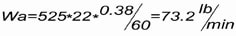
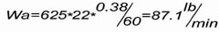
I have a 6.6 liter diesel engine that makes a claimed 325 flywheel horsepower (about 275 wheel horsepower as measured on a chassis dyno). I would like to make 425 wheel hp; an increase of 150 wheel horsepower. Plugging these numbers into the formula and using the AFR and BSFC data from above:
Recall from Turbo Tech 103:
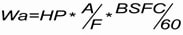
- Where,
- Wa = Airflowactual (lb/min)
- HP = Horsepower Target (flywheel)
- A/F = Air/Fuel Ratio
- BSFC/60 = Brake Specific Fuel Consumption (lb/(Hp*hr))/60 (to convert from hours to minutes)
So we will need to choose a compressor map that has a capability of at least 59.2 pounds per minute of airflow capacity. Next, how much boost pressure will be needed?
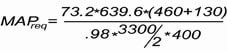
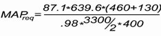
Calculate the manifold pressure required to meet the horsepower target.
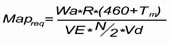
- Where,
- MAPreq = Manifold Absolute Pressure (psia) required to meet the horsepower target
- Wa = Airflowactual (lb/min)
- R = Gas Constant = 639.6
- Tm = Intake Manifold Temperature (degrees F)
- VE = Volumetric Efficiency
- N = Engine speed (RPM)
- Vd = engine displacement (Cubic Inches, convert from liters to CI by multiplying by 61, ex. 2.0 liters * 61 = 122 CI)
- For our project engine:
- Wa = 59.2 lb/min as previously calculated
- Tm = 130 degrees F
- VE = 98%
- N = 3300 RPM
- Vd = 6.6 liters * 61 = 400 CI
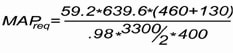
= 34.5 psia (remember, this is absolute pressure; subtract atmospheric pressure to get gauge pressure, 34.5 psia – 14.7 psia (at sea level) = 19.8 psig)
So now we have a Mass Flow and Manifold Pressure. We are almost ready to plot the data on the compressor map. Next step is to determine how much pressure loss exists between the compressor and the manifold. The best way to do this is to measure the pressure drop with a data acquisition system, but many times that is not practical. Depending upon flow rate and charge air cooler size, piping size and number/quality of the bends, throttle body restriction, etc., you can estimate from 1 psi (or less) up to 4 psi (or higher). For our examples we will estimate that there is a 2 psi loss. Therefore we will need to add 2 psi to the manifold pressure in order to determine the Compressor Discharge Pressure (P2c).
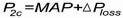
-
- Where,
- P2c = Compressor Discharge Pressure (psia)
- MAP = Manifold Absolute Pressure (psia)
 = Pressure loss between the Compressor and the Manifold (psi)

- = 36.5 psia
To get the correct inlet condition, it is now necessary to estimate the air filter or other restrictions. In the Pressure Ratio discussion earlier we said that a typical value might be 1 psi, so that is what will be used in this calculation. Also, we are going to assume that we are at sea level, so we are going to use an ambient pressure of 14.7 psia. We will need to subtract the 1 psi pressure loss from the ambient pressure to determine the Compressor Inlet Pressure (P1).
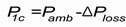
-
- Where:
 = Compressor Inlet Pressure (psia)
 = Ambient Air pressure (psia)
- = Pressure loss due to Air Filter/Piping (psi)

- = 13.7 psia
With this, we can calculate Pressure Ratio ( ) using the equation.
For the 2.0L engine:

= 2.7
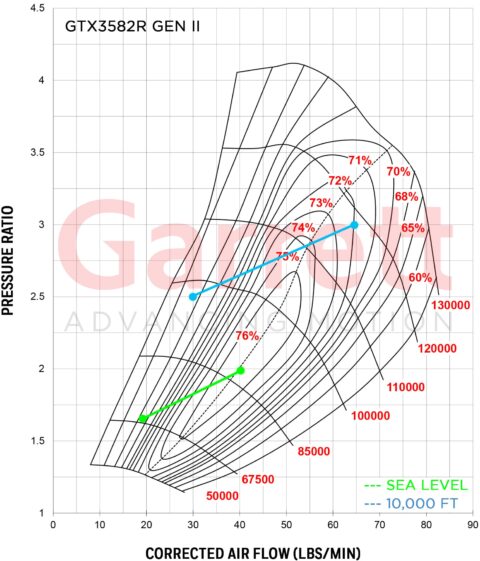
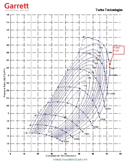
We now have enough information to plot these operating points on the compressor map. First we will try a GT3788R. This turbo has an 88mm tip diameter 52 trim compressor wheel with a 64.45 mm inducer.
As you can see, this point falls nicely on the map with some additional room for increased boost and mass flow if the horsepower target climbs. For this reason, the GT37R turbo family is applied on many of the Garrett Powermax turbo kits that are sized for this horsepower range.
For the next example, let’s look at the Weekend Warrior. This category is for daily driven vehicles that have up to 250 horsepower over stock or 525 wheel horsepower.
Plugging that power target into our formula yields an airflow requirement of:
And a pressure ratio of:

= 45.5 psia
= 3.3
Looking at the previous map, the compressor does not flow enough to support this requirement, so we must look at the next larger size compressor.
(Technically, the engine could probably easily make this power with the previous compressor, but it would be at risk of more smoke, higher EGT’s and backpressure; kind of like pushing a stock compressor too far…)
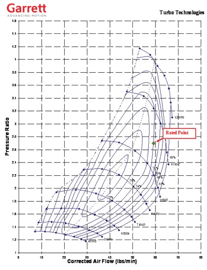
The next larger turbo is a GT4094R and is shown below.
Another option that could also be considered is the GT4294R which has a slightly larger inducer compressor and the next larger frame size turbine wheel.
The larger wheel inertia’s will slow down the response a bit, but provide better performance at the top end of the rpm range.
For the next example, let’s look at the Extreme Performance. This category is for real hot rod vehicles that have up to 350 horsepower over stock and owners that are willing to give up some of the daily utility in order to achieve higher power gains.
Plugging that power target into our formula yields an airflow requirement of:
And a pressure ratio of :
= 50.8 psia

= 52.8 psia
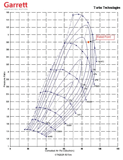
=3.8
For this flow and pressure ratio, the GT4202R is appropriate and is shown below. Since this is approaching a pressure ratio of 4-to-1, we are about at the limit of a single turbo on an engine of this size.
Final Case: Competition Category
The final case is the Competition category. Since this is a special case and there are so many ways to go about an ultimate power diesel application, it is not possible to cover it adequately in this article. There are, however, some general guidelines. At this power level, as stated above, it is a good idea to consider a series turbo application. This is a situation where one turbo feeds another turbo, sharing the work of compressing the air across both compressors. A larger turbo is designated as the “low-pressure” turbo and the smaller secondary stage as the “high pressure” turbo. The low-pressure compressor feeds the high-pressure compressor which then feeds the intake. On the turbine-side the exhaust first passes through the high-pressure turbine and then on to the low-pressure turbine before being routed out through the tailpipe. We can still calculate the required mass flow, but the pressure ratio is more involved and questions should be discussed with your local Garrett Powermax distributor. To calculate the required mass flow, we use the normal equation. This time the power target will be 500 wheel horsepower over stock, for a total of 775 wheel horsepower
This air flow rate will apply only to the low-pressure compressor as the high-pressure compressor will be smaller because it is further pressurizing already compressed air. In most cases, the high-pressure turbo tends to be about two frame sizes smaller than the low pressure stage. So in this case, after selecting the appropriate low-pressure turbo (hint: look at the GT4718R compressor map), a GT4088R or GT4094R would be the likely candidates.
One more comment on choosing a properly sized turbine housing A/R. A smaller A/R will help the turbo come up on boost sooner and provide a better responding turbo application, but at the expense of higher back pressure in the higher rpm zones and, in some cases, a risk of pushing the compressor into surge if the boost rises too rapidly. On the other hand, a larger A/R will respond slower, but with better top end performance and reduced risk of running the compressor into surge. Generally speaking, the proper turbine housing is the largest one that will give acceptable boost response on the low end while allowing for more optimal top end performance.
This information should be used as a starting point for making decisions on proper turbo sizing. Of course, for more specific information on your engine, consult a Garrett Powermax distributor.