


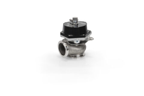
Garrett GVW External Wastegates:
Features:
- CFD tested for maximum flow and thermal efficiency
- Optimized actuation stability and temperature resistance for superior durability
- Replaceable valve and bushing components to increase service life
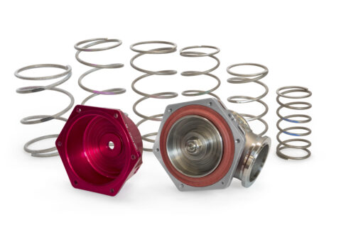
- Robust design for easy diaphragm replacement
- Liquid-cooled actuator ports for use on severe applications (up to 52% reduction in body temp)
- Anodized aluminum actuator cover
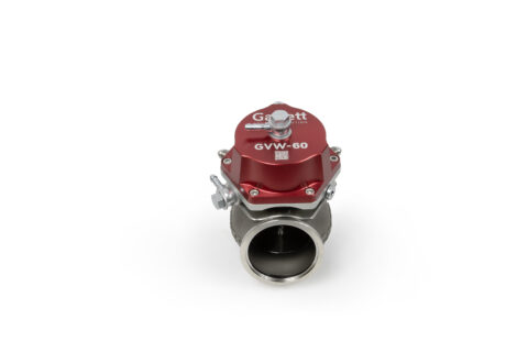
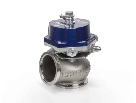
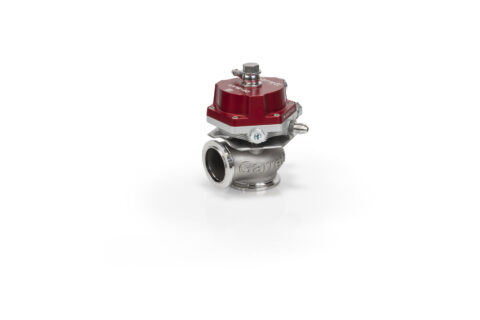
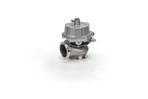
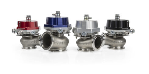
- Four Colors: Red | Blue | Black | Silver
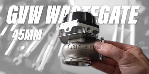
- Three Sizes: 40mm | 45mm | 50mm | 60mm
- Springs | Fittings | Flanges | V-Bands included
- Standard Base Pressure: 1 Bar | 14.5 PSI
- Maximum Base Pressure:
GVW-40: 25 PSI | 1.7 Bar
GVW-45 | GVW-50 | GVW-60 23 PSI | 1.6 Bar - Minimum Base Pressure: 3 PSI | 0.2 Bar
Part Numbers
Garrett GVW External Wastegates: Part Numbers and Configurations
| Model | Red | Blue | Black | Silver | Base Pressure | Spring Chart | Install Guide |
|---|---|---|---|---|---|---|---|
| GVW-40 | 908827-0001 | 908827-0002 | 908827-0003 | 908827-0004 | 1 Bar | 14.5 PSI | Download | Download |
| GVW-45 | 908828-0001 | 908828-0002 | 908828-0003 | 908828-0004 | 1 Bar | 14.5 PSI | Download | Download |
| GVW-50 | 908829-0001 | 908829-0002 | 908829-0003 | 908829-0004 | 1 Bar | 14.5 PSI | Download | Download |
| GVW-60 | 908830-0001 | 908830-0002 | 908830-0003 | 908830-0004 | 1 Bar | 14.5 PSI | Download | Download |
Garrett GVW Customer Reviews
Garrett GVW Wastegates Installed by Drift HQ’s Kris Lawrence
The Garrett GVW Wastegates are the newest option for reliable boost control of turbocharged engines.

HTP Performance Builds Turbo Hayabusa With G-Series Turbo
HTP engineered and manufactured the “HyperBusa” performance kit and outfitted this bike with a G-Series G30-770 turbocharger and a 45mm Garrett GVW external wastegate. The bike was calibrated and dyno’d at HTP performance on different fuel and boost pressures allowing for multiple power settings.
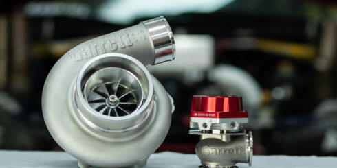
Garrett Motion Releases New External Wastegate Product Line
Through the Garrett Performance network you can get turbos to create the boost, intercoolers to cool the boost, and external wastegates to control the boost.
GARRETT RELEASES VENT LINE OF EXTERNAL WASTEGATES FOR PERFORMANCE AND RACING USE
Garrett | Vent External Wastegates are offered in 40mm 45mm and 50mm sizes. See how our development in Indy Car helped in development
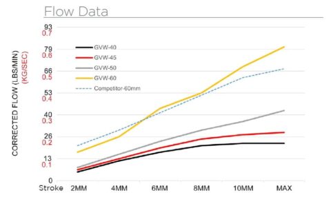
Flow Data
Garrett engineers created GVW as a high flowing product with low degradation in performance over its lifespan. Here’s how the three GVW wastegate sizes flow in LBS/MIN and KG/SEC at various increments of the valve stroke.
Material Data
The valve housing is cast from high temp stainless steel and rated for exhaust temperatures up to 1050° C. CFD optimized for maximum flow and thermal efficiency.
- Valve Housing: High temp stainless steel rated up to 1050° C
- Diaphragm: High temp Nomex reinforced elastomer
- Actuator Cover: Fully-machined anodized 6061 aluminum
- Valve Guide | Bushing: Nitronic 60
- Valve: high temp stainless steel with plated stem
- V-Band: CNC machined 304 stainless steel
- Flanges: Fully-machined 304 stainless steel
- Springs: 17/7 PH stainless steel
Mechanical Data
Garrett Vent | External Wastegates are created by the engineers that designed G-Series and GTX Gen II turbochargers. Available in three sizes: 40mm | 45mm | 50mm
- Valve Diameter: 40mm | 45mm | 50mm | 60mm
- Valve Mass: (40mm)1.27kg | 45oz (45mm) 1.47kg | 52oz (50mm) 1.56kg | 55oz (60mm) 1.74kg | 61oz
- Max Spring Base Pressure: 1.7 bar | 25 psi (1:1 backpressure ratio)
- Minimum Spring Base Pressure: 0.2 bar | 3 psi (1:1 backpressure ratio)
- Port Fitting | Air: M10x1.0 to hose barb (hose ID 6mm | .25in)
- Port Fitting | Water: M8x1.0 to AN-3
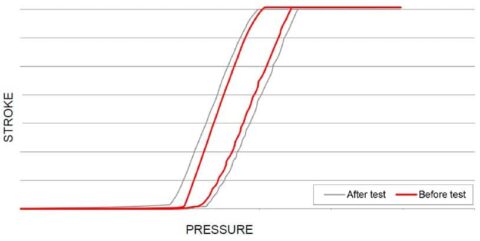
Thermal Data
When researching and testing common shortfalls of wastegates, we observed how heat cycling and normal wear can rapidly change their actuation characteristics. Garrett engineers created GVW as a high flowing product with low degradation in performance over its lifespan. Actuation data (opening and closing) in the chart was measured before and after extreme testing conditions. Results show the heat cycled GVW product maintains linear control of the wastegate as compared to the new product. Precise actuation of the GVW provides accurate calibration settings and performance throughout the lifespan of the product. Accurate wastegates, allow for optimum performance of the turbocharger.
- Max Thermal Stress (non-cooled): 270°C actuator body temp during thermal cycle test
- Max Thermal Stress (liquid-cooled): 130°C actuator body temp during thermal cycle test
- Max Exhaust Temp | Peak: Up to 1050°C
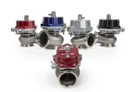
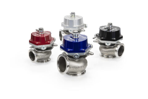
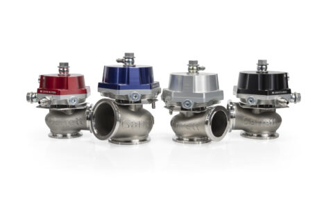
4 Color and 4 Size Options
GVW Wastegates are available in four colors and three sizes
- Sizes: 40mm | 45mm | 50mm | 60mm
- Colors: Red | Black | Blue | Silver
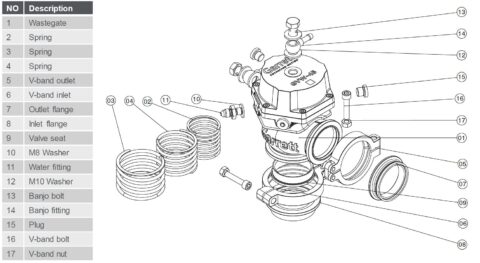
Kit Contents
GVW Wastegates include all the following parts:
- Springs
- V-Band: Inlet | Outlet
- Outlet Flange
- Inlet Flange
- Valve Seat
- Washers: M8 | M10
- Water Fittings
- Banjo Bolt and Banjo Fittings
- Air Plugs
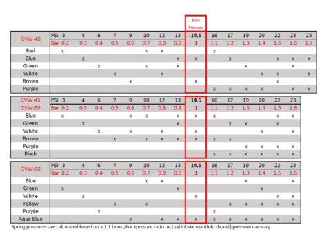
Wastegate Springs
GVW wastegates are set to 1 Bar | 14.5 PSI of base pressure and can be configured from 0.2 Bar | 2.9 PSI – 1.7 Bar | 24.7 PSI (considering 1:1 backpressure).
Use the chart to reference wastegate size and spring color to identify Garrett GVW wastegate spring pressures
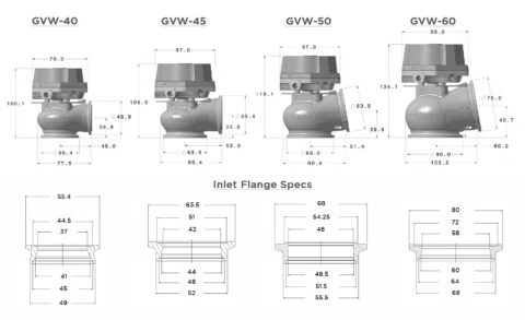
Wastegate Flange Specs
GVW Wastegate flanges can be references in this data:
- GVW-40: Inlet OD 55.4mm | 2.18in Outlet OD 48.9mm | 1.93in (Interchangeable with Tial MV-S, MV-R)
- GVW-45: Inlet OD 63.5mm | 2.50in Outlet OD 55.4mm | 2.18in (Interchangeable with Tial MV-S, MV-R)
- GVW-50: Inlet OD 68.0mm | 2.68in Outlet OD 63.5mm | 2.50in (Interchangeable with Turbosmart Gen V ProGate 50)
- GVW-60: Inlet OD 80.0mm | 3.15in Outlet OD 75mm | 2.95in (Interchangeable with Turbosmart Gen V PowerGate 60)
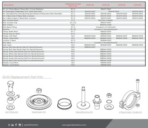
Serviceability- Replacement Kits
Replacement part kits are available for GVW wastegates. See chart for part numbers and torque specs.
- Air Fitting Kit (Banjo fitting, bolt, 2 crush washers)
- Diaphragm Kit (Diaphragm assembly, valve stem nut)
- Valve | Bushing Kit (Valve, bushing, seal washer, O-ring, valve stem nut, seat)
- V-Band Inlet (V-Band, bolt, locknut)
- V-Band Outlet (V-Band, bolt, locknut)
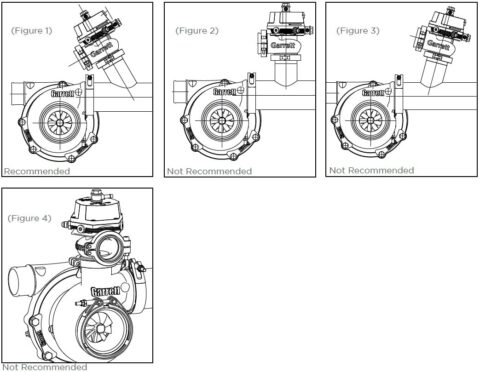
GVW Wastegate Placement Suggestions
Wastegate placement on the exhaust manifold is a key factor in wastegate performance. The following suggestions can help identify the best choice when purchasing or fabricating an exhaust manifold for your project. The connection on the manifold greatly affects flow capability, and correct orientation of the wastegate to the manifold is essential.
The ideal connection is at 45° with a smooth transition (Figure 1). Placing the wastegate at 90° to the manifold (Figure 2) will reduce flow capacity by up to 50 percent and can cause over boosting! More reduction in flow capacity will result if the wastegate is placed at angles greater than 90° (Figure3). Figures 2 and 3 greatly reduce the control you have over the system and can put your entire drive train at risk. Never mount the wastegate to the turbine housing at any time, this will reduce the performance of the turbocharger (Figure 4). Contact an authorized distributor for additional information.
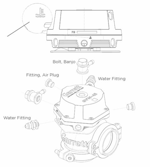
Wastegate Port Fittings
GVW wastegates feature a water-cooling circuit which allows the product to be operated in extremely high temperature conditions while maintaining its actuation characteristics. Water-cooling symbols are etched near both of the fitting ports for easy identification. If watercooling, both ports must be used to create a coolant loop. (2) Water fittings and (2) washers are included and can be installed with a 14mm wrench or socket.
There are two air ports on the top cap and three air ports on the valve body. (2) 14mm Banjo fittings with washers and (3) 5mm hex head air plugs are included. Please see the boost control section for more information on how to install the port fittings based on your application.
Changing Wastegate Springs
Wastegate springs are under pressure and can cause bodily harm if improperly installed. Please wear eye protection. If you have any doubts as to your ability to install this product, consult a local automotive repair company.
Remove the wastegate from the manifold. Place wastegate into an arbor press and depress the ram so it creates downward pressure on the top banjo fitting. The ram should be centered over the banjo. Remove the (6) 3mm hex-head screws in the top cap while maintaining pressure on the ram as to keep the cap from lifting off the body.
Once all 6 screws are removed, slowly raise the ram on the arbor press to release the pressure on the springs. Using the spring chart below, identify the appropriate springs you wish to install. GVW wastegates are assembled to 1 Bar | 14.5 PSI.
The springs must sit properly in the grooves to align the diaphragm assembly and actuator cover. Improper placement of the springs may result in failure of the wastegate. Set replacement springs in the diaphragm assembly grooves. Place top cap on and align the longest spring with the appropriate groove in the cap.
Place the wastegate in the arbor press and center it under the ram. Lower the ram slowly until the top cap touches the actuator body. Align the holes in the top cap with the threaded holes on the bottom cap, then install the (6) 3mm hex-head crews. Once all (6) screws are tight, raise the ram, remove the wastegate and torque the hex-head screws to 2.5Nm | 2.0 ft-lb.

Changing The Wastegate Diaphragm
Wastegate springs are under pressure and can cause bodily harm if improperly installed. Please wear eye protection. If you have any doubts as to your ability to install this product, consult a local automotive repair company.
Remove the wastegate from the manifold. Remove all fittings from the top cap. Place wastegate into an arbor press and depress the ram so it creates downward pressure on the top cap. The ram should be in the center of the cap. Remove the (6) 3mm hex-head screws in the top cap while maintaining pressure on the ram as to keep the cap from lifting off the body.
Once all 6 screws are removed, slowly raise the ram on the arbor press to release the pressure on the springs. Remove the top cap and springs. Insert an 8mm hex key into the opening at the bottom of the valve, use a 13mm socket and ratchet to loosen and remove the valve stem nut. While supporting the valve in the up position, remove the old diaphragm and set the new on in place making sure the spring seat grooves face up. Hand thread on the new valve stem nut. Using the 8mm hex, and 13mm socket and ratchet, torque the nut to 10 Nm | 7 ft-lb.
Reinstall the springs and cap. The springs must sit properly in the grooves to align the diaphragm assembly and actuator cover. Improper placement of the springs may result in failure of the wastegate. Set replacement springs in the diaphragm assembly grooves. Place top cap on and align the longest spring with the appropriate groove in the cap. Place the wastegate in the arbor press and center it under the ram. Lower the ram slowly until the top cap touches the actuator body. Align the holes in the top cap with the threaded holes on the bottom cap, then install the (6) 3mm hexhead crews. Once all (6) screws are tight, raise the ram, remove the
wastegate and torque the hex-head screws to 2.5Nm | 2.0 ft-lb.

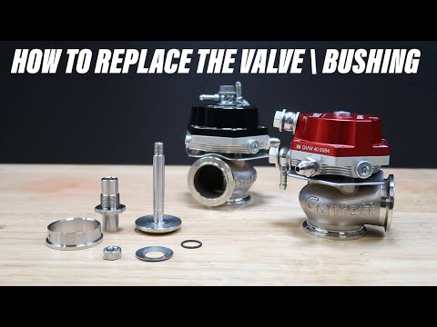
Changing The Wastegate Valve / Bushing
Wastegate springs are under pressure and can cause bodily harm if improperly installed. Please wear eye protection. If you have any doubts as to your ability to install this product, consult a local automotive repair company.
Remove the wastegate from the manifold. Remove all fittings from the top cap. Place wastegate into an arbor press and depress the ram so it creates downward pressure on the top cap. The ram should be in the center of the cap. Remove the (6) 3mm hex-head screws in the top cap while maintaining pressure on the ram as to keep the cap from lifting off the body.
Once all 6 screws are removed, slowly raise the ram on the arbor press to release the pressure on the springs. Remove the top cap and springs. Insert an 8mm hex key into the opening at the bottom of the valve, use a 13mm socket and ratchet to loosen and remove the valve stem nut. While supporting the valve in the up position, remove the diaphragm. Next, remove the valve. Remove the (3) 3mm hex-head screws from the actuator body. Remove the actuator body. Be careful not to lose the (3) spacers, (1) O-ring, (1) disc spring, or heat shield as these will move freely once the actuator body and actuator body screws are removed. Place actuator housing into a vise and use a 24mm socket and ratchet to loosen and remove the bushing. Replace the bushing and torque to 30 Nm | 22 ft-lb.
Set the heat shield on the actuator housing with the rolled edge over the outlet. Place (3) spacers over each threaded hole. Slide the disc spring over the bushing stem. Slide the o-ring over the bushing stem. Place actuator body over the bushing stem with the preferred port orientation. Double check alignment of the spacers then install (3) 3mm hex-head screws making sure the screw goes through each spacer. Torque to 5 Nm | 4 ft-lb.
Insert the valve into the bushing and set the diaphragm on top making sure the spring seat grooves face up. Hand thread on the new valve stem nut. Using the 8mm hex, and 13mm socket and ratchet, torque the nut to 10 Nm | 7 ft-lb. Reinstall the springs and cap. The springs must sit properly in the grooves to align the diaphragm assembly and actuator cover. Improper placement of the springs may result in failure of the wastegate. Set replacement springs in the diaphragm assembly grooves. Place top cap on and align the longest spring with the appropriate groove in the cap. Place the wastegate in the arbor press and center it under the ram. Lower the ram slowly until the top cap touches the actuator body. Align the holes in the top cap with the threaded holes on the bottom cap, then install the (6) 3mm hex-head crews. Once all (6) screws are tight, raise the ram, remove the wastegate and torque the hex-head screws to 2.5Nm | 2.0 ft-lb.