


Accessing the Knowledge Center effectively requires a simple, one-time registration.
Diving into the Distinctions Between Turbo Types
Turbochargers, like other mechanical devices like engines, have a technical history where subsequent innovations developed into new technical iterations, or types, built upon the previous generation.
Nearly all main turbo types fall into a “turbo family”:
- free floating,
- wastegate,
- variable nozzle turbine (VNT, and sometimes called variable geometry turbine,
- electric turbos (E-Turbos).
In this article, we will review these different turbocharger types beginning with the simplest/earliest types to most recent.
![]()
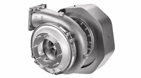
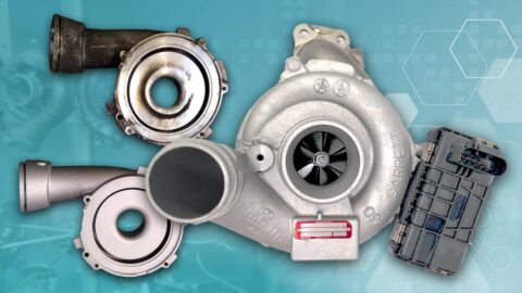
Free Floating: A turbocharger with a single, fixed area-to-radius (also called A over R, or A/R) is called a free-floating or fixed geometry turbo, because it has no integral control over speed or boost pressure. Turbo control is entirely dependent on the engine and its systems providing the correct amount of energy in the exhaust gas to power to the turbine. The turbocharger is precisely matched to the engine during the engine development phase, where the optimum A/R turbine housing is selected.
This type of turbo was the earliest developed but has become specialized in recent years to produce maximum levels of power and torque using the most robust materials and turbo construction methods for the biggest land-use engines in the world, specifically in off-road earth moving and construction equipment between 64-liters and 110-liters of displacement. Just because these types of turbos are the simplest designs doesn’t mean they don’t use the latest technology; in fact, new free-floating turbos often use titanium wheels and high nickel cobalt tungsten alloys to maintain durability up to 20,000 hours.
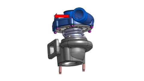
Wastegate: The wastegate or turbine bypass was introduced onto our turbochargers many years ago, to improve turbo and engine performance. These types of devices were used as early as the 1940s in the Wright R-1820 Cyclone engine found on the famous B-17 Flying Fortress (pilots could manually control wastegate operation their B-17s superchargers).
![]()
A wastegate turbo contains several additional components providing control over the exhaust gas bypass flow. An internal wastegate valve is mounted on an arm which passes through a bush in the turbine housing. An external crank assembly is welded to it. This crank is controlled by either a pneumatic or electric actuator.
A pneumatic actuator may be powered by air pressure or vacuum and controlled by a hose from the compressor outlet or by a control valve in the vehicle’s vacuum circuit. An electric actuator responds to commands from the vehicle’s own Electronic Control Unit.
The wastegate allows a controlled flow of exhaust gas to bypass the turbine wheel. This allows the use of a smaller A/R turbine housing for maximum acceleration of the turbine at low engine speeds when the wastegate valve is closed.
At higher engine speeds, when the turbine housing approaches its maximum flow, the wastegate valve opens to allow some exhaust gas to bypass the turbine wheel and merge directly with the exhaust outlet flow.
This increases the flow capacity of the housing, reducing back pressure and allowing the engine to breathe freely for maximum power. So, the compromise of fixed geometry is reduced offering higher engine power with improved low speed response.
In the simplest wastegate control circuit, a pressure actuator is connected directly to the compressor outlet by a hose. When the turbo is operating at low speed and low boost level, the pressure in the hose and the actuator is also low, so the turbine bypass valve is closed.
When the vehicle driver accelerates, the turbo responds to the increasing energy in the exhaust gas by speeding up and providing more boost pressure and air flow to the engine. When this boost pressure reaches a pre-determined level, this causes the actuator rod to move and open the turbine bypass valve, allowing the excess exhaust gas to flow directly into the vehicle exhaust system.
When the driver decelerates, the boost pressure from the turbo reduces and the bypass valve closes again.
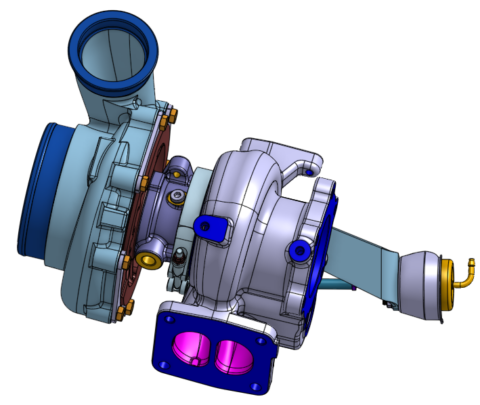
![]() Variable Nozzle Turbine (VNT): Variable Turbine technology is much more complex than Wastegate technology. The turbocharger is designed to maximize boost across the whole operating range of the engine, eliminating turbo lag.
Variable Nozzle Turbine (VNT): Variable Turbine technology is much more complex than Wastegate technology. The turbocharger is designed to maximize boost across the whole operating range of the engine, eliminating turbo lag.
It uses complex precision variable vane or nozzle technology. These moving parts are controlled by pressure, vacuum or electronic actuators linked to the engine management system.
Garrett patented the idea in 1953; but not until the late 1980s were VNT turbos commercially deployed in the 1988 Honda Legend and 1989 Shelby Daytona CSX-VNT. The really first successful launch came on a diesel engine a few years later in 1991 on the Fiat Croma’s direct injection turbo-diesel.
So successful was the VNT on turbo-diesels in particular that almost all modern turbo-diesels for passenger vehicles use VNT, along with direct fuel injection.
The turbine housing chosen to suit the maximum rated power of the engine and then by moving the vanes and varying the size of the gas passage into the wheel, this effectively gives a constantly variable range of A/R, offering greatly improved performance over a wider engine operating range.
Movement of the vanes is controlled by an actuator connected to an external crank assembly. This crank connects via a short shaft, to the internal control arm and transfers movement to a unison ring, which controls the movement of all the vanes by means of their vane arms.
In the minimum flow position, the exhaust gas is accelerated through the vanes to higher velocity in a similar way to a small A/R housing, to give maximum acceleration of the turbine and compressor with fast boost pressure rise. As engine speed and load increases, the vanes move towards the fully open position to give maximum flow capacity and reduced back pressure for better engine breathing in a similar way to a large A/R housing.
On a modern VNT turbo, the vane position is constantly and rapidly changing in response to signals from the vehicle ECU to comply not only with the driver’s commands, but with the many inputs controlling combustion efficiency and exhaust emissions.
Our VNT represented a step change in turbocharger performance compared to the aforementioned free-floating and wastegated turbos.
![]() E-Turbos: Electronic turbos, or e-turbos, represent a quantum leap in turbo technology for the 21st Century. Up until the e-turbo, all of the energy used to power the turbine and compressor wheels came from otherwise wasted exhaust gases; while the e-turbo still makes use of exhaust gases as engine speeds rise, the e-turbo—as might be expected—is driven by a small electric motor.
E-Turbos: Electronic turbos, or e-turbos, represent a quantum leap in turbo technology for the 21st Century. Up until the e-turbo, all of the energy used to power the turbine and compressor wheels came from otherwise wasted exhaust gases; while the e-turbo still makes use of exhaust gases as engine speeds rise, the e-turbo—as might be expected—is driven by a small electric motor.
One of the key enablers of the e-turbo is the small but ongoing shift from traditional 12 volt electrical systems to 48 volt systems typical in mild hybrid power-trains. Until now, there just wasn’t enough juice to run the small electric motor needed to quickly spool up the turbo, but 48 volt systems overcome this obstacle.
Not only can turbos be better sized to serve up better performance across the rev range of the engine, but the e-turbo has the potential to serve as an electrical generator to capture and store otherwise wasted heat exhaust energy as electrical energy by charging the battery under certain conditions.
As the world moves toward more electrified power-trains, including more mild hybrids, we should expect to see a quickly growing number of e-turbos in the marketplace over the next several years.
Also, if you want to learn more about turbochargers, try our Installer Connect training modules and earn completion certificates.
See Other Relevant Content from Knowledge Center