


TURBOCHARGER SYSTEM CHECK
HOW DOES TURBOCHARGER WORKS ?
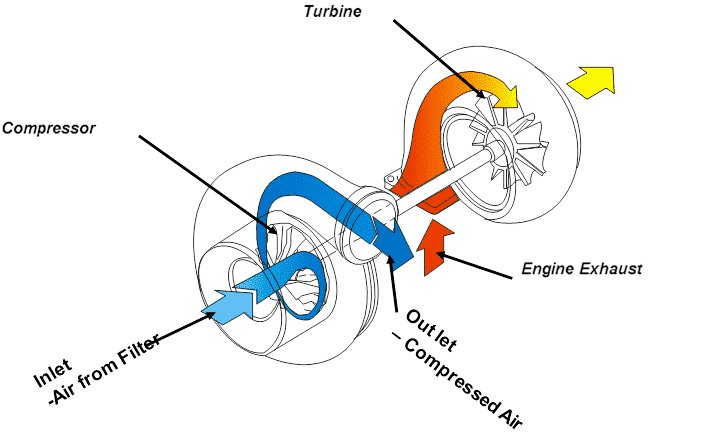
High temperature, high pressure exhaust gases from the engine enter the turbine housing and drive the turbine wheel. The turbine wheel is connected to the compressor wheel with a solid shaft. The rotation of the compressor wheel compresses the ambient air and forces it into the engine. This increases the amount of fuel that can be burnt, increasing the efficiency and power output of the engine.
BENEFITS OF TURBOCHARGING
 Increased power output of the engine
 Engine power retained at altitude
 Reduced engine size and weight
 Reduced emissions
 Reduced fuel consumption
 Reduced cost of ownership
TURBOCHARGER PART DESCRIPTION
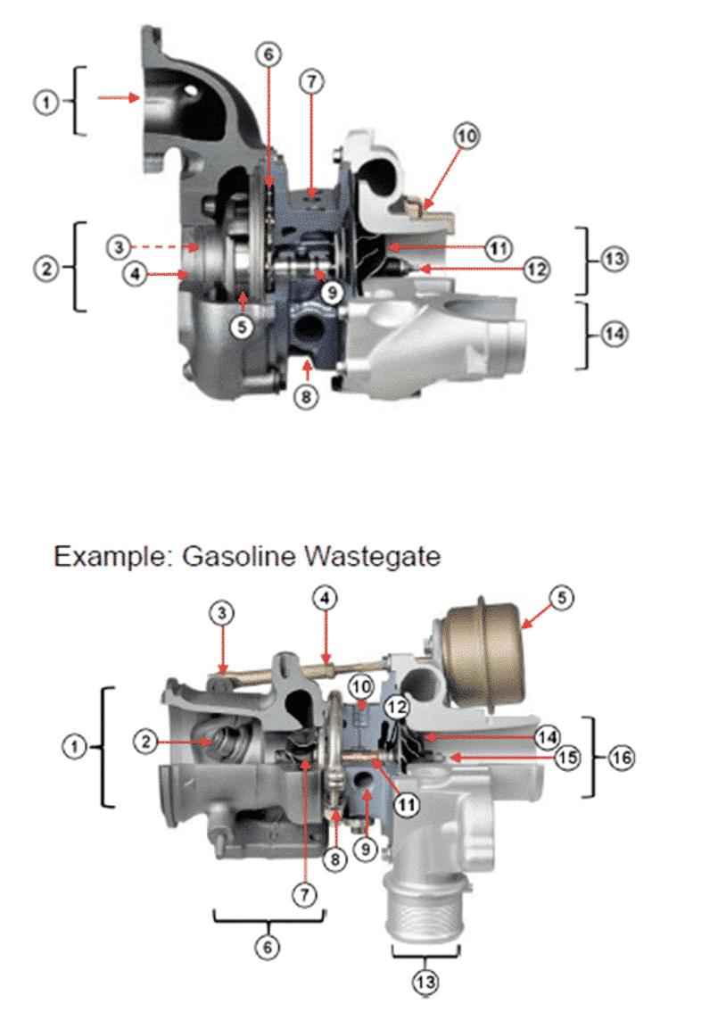
- Turbine gas inlet
- Turbine gas outlet
- Turbine wheel (hidden)
- Cartridge
- Vanes
- Unison ring
Example: Gasoline Wastegate
- Turbine gas outlet
- Wastegate valve
- Wastegate crank
- Actuator rod
- Pneumatic actuator body
- Turbine gas inlet
- Turbine wheel
- V-band
- Center housing oil outlet
- Center housing oil outlet
- Center housing oil inlet
- Bearing
- Electric actuator
- Compressor wheel
- Shaft
- Center housing oil inlet
- Bearing
- Piston ring
- Compressor air outlet
- Compressor wheel
- Shaft
- Compressor air outlet