


Accessing the Knowledge Center effectively requires a simple, one-time registration.
Turbocharger Bearing Systems
The turbo bearing system may appear simple in design, with one or two bronze bearings – and sometimes a separate thrust bearing, but it plays a key role – ensuring that wheels keep spinning without any housing contact.
Behind this deceptively simple design is the reality is that the design, materials and manufacturing processes used to create the bearing system have been refined constantly to keep pace with the new levels of turbocharger performance demanded by advanced engine design.
Just think about what we are asking the bearings to do:
- Offer both support and damping to control the radial and axial motion of the shaft and wheels.
- Isolate vibration from the rotating parts.
- Allow the turbo wheels to spin at speeds 60 times faster than the maximum engine speed found in a typical modern diesel engine.
- Ensure that the maximum energy from the engine exhaust gas is available to drive the turbo and is not wasted in the bearing system
- Work effectively with the latest oils, in order to reduce friction and power losses in modern engines
- Work effectively with today’s higher engine oil temperatures.
The bearing systems in turbos need to balance low power losses with the ability to control the huge forces applied by the constantly varying mechanical loadings.
Modern turbo bearing systems split into two types:
- Hydrodynamic bearing systems – used in the vast majority of past and present turbos
- Ball bearing systems – previously used only for racing and fast road applications, but launched on production VNT™ turbos for passenger vehicles.
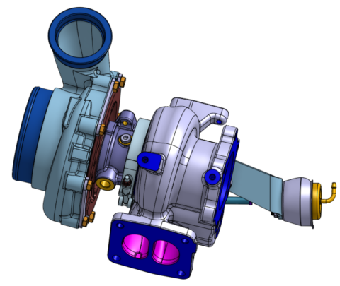
In a turbocharger hydrodynamic bearing system, the fluid (engine oil) not only lubricates the parts, preventing contact, but also controls the motion of the shaft and wheels under all running conditions.
The hydrodynamic bearing system may use two “fully floating” journal bearings, which rotate at approximately half the speed of the shaft. There are two hydrodynamic oil films; an outer one, between the center housing and bearing, and an inner film between the bearing and the shaft.
Most small, high speed passenger vehicle turbos use a one piece “semi-floating” bearing which does not rotate. This design also uses two oil films, but in this case the outer oil film acts mainly as a “squeeze film” for damping shaft motion. On this bearing, there is only one hydrodynamic oil film (between shaft and bearing), and this leads to improved control of the rotor assembly.
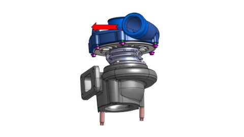
A thrust bearing controls the axial motion of the rotor assembly, which may be a separate part or integrated into the journal bearing, as in the case of the one piece “Z-Bearing”. In all designs, high pressure is generated in the thrust pad area to control axial movement. The Z-bearing also contains features designed to optimize performance with modern low viscosity oils.
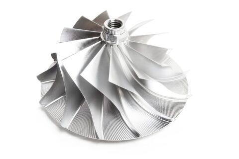
Ball bearings combine the functions of journal and thrust bearings into a single package. The reduced clearances allow for improved turbine and compressor performance, while the lower power losses within the bearing improve overall performance. The latest VNT™ ball bearing turbo uses a new ceramic ball bearing cartridge – a development that takes performance enhancement to a whole new level.
Want to expand your knowledge in the turbo space? Join a community with mechanics who are eager to learn and show their skills. Boost your skills with our Training connect levels and take your certification today! All in the Garrett Connect App.
See Other Relevant Content from Knowledge Center