


Garrett Performance Intercoolers
Garrett performance intercoolers are engineered with meticulous engineering standards to deliver thermal stability for high boost performance systems. From direct fit upgrades for popular turbocharged vehicles to a broad range of core sizes for fabrication projects, Garrett supports end users, dealers, kit makers, and builders with engineered charge air cooling solutions.
Use this page to explore vehicle specific upgrades, evaluate intercooler core sizing options, and select the best cooling solution for your build.
Vehicle SpecificAir-to-Air Cores
Air-to-Liquid Cores
Options
Range
Plate
Built for Performance. Designed for Builders.
Garrett intercoolers are engineered to deliver high thermal effectiveness, structural durability, and airflow balance under sustained boost. Whether upgrading a popular turbocharged vehicle or fabricating a custom high-horsepower build, our intercooler solutions are designed to meet demanding performance standards.
From direct-fit vehicle-specific upgrades to a comprehensive range of bar-and-plate intercooler cores, Garrett supports end users, dealers, kit makers, and fabricators with scalable cooling solutions.

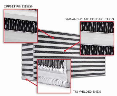
Inside Garrett Intercooler Core Engineering
Garrett bar-and-plate intercooler cores utilize optimized internal fin density and flow passages to maximize heat transfer while maintaining controlled pressure drop.
Fin density is carefully selected based on flow path balancing surface area for thermal transfer with airflow efficiency to support repeatable performance under sustained boost conditions.
- Bar-and-Plate Construction
- Offset Fin Design
- Hot & Cold Flow Optimization
- Balanced Pressure Drop Management
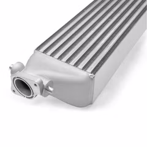
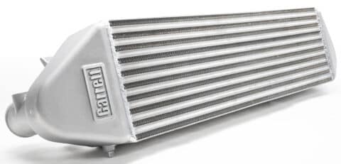
Vehicle Specific Performance Intercoolers
Fitment
Direct fit installation
Cooling
Increased thermal capacity
Consistency
Reduced heat soak
Use Case
Built for sustained boost
| Part Number | Application | Horsepower* |
|---|---|---|
| 857564-6001 | 2015+ Mustang 2.3L EcoBoost | Up to 600 |
| 870702-6001 | 2015+ 3.5L | 2.7L Ford F 150 C.A.R.B Certified | Up to 750 |
| 880736-6001 | 2013 to 2018 2.0L Ford Focus ST | Up to 670 |
| 891185-6001 | 2015+ Subaru WRX 2.0L | Up to 530 |
| 881649-6001 | 2011 to 2021 Ford Ranger | Everest | Mazda BT50 | Up to 499 kW |
| 888883-6002 | 2015+ BMW M3 and M4 F80 F82 F83 | Up to 980 |
| 893516-6001 | 2016+ Honda Civic 1.5L T Si | Up to 660 |
Installation instructions are available on each individual product page. Horsepower ratings shown for typical operating conditions. Maximum horsepower potential may exceed listed values depending on setup and calibration.
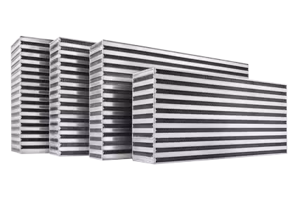
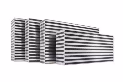
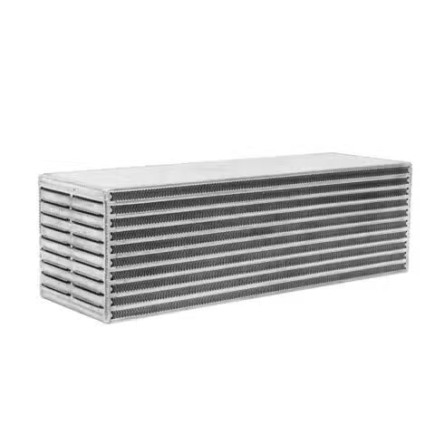
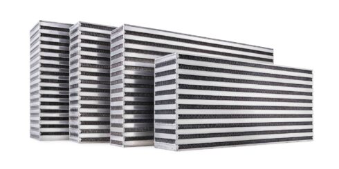
Air-To-Air Intercooler Cores
Garrett Air-to-Air intercooler cores support aftermarket fabrication projects that require high thermal efficiency, controlled pressure drop, and durable construction under sustained boost. Select core size based on packaging constraints and horsepower targets.
Length hot flow is the charge air flow length through the core.
Height no flow is the external core height dimension.
Width cold flow is the external core thickness dimension.
For packaging, start with available space, then choose the highest supported horsepower core that fits your build requirements.
| Part Number | FLow | Supported Horsepower | Length Hot Flow | Height No Flow | Width Cold Flow | |||
|---|---|---|---|---|---|---|---|---|
| in | mm | in | mm | in | mm | |||
| 848054-6012 | Horizontal | 300 | 10.2 | 260 | 8.1 | 205 | 4.7 | 120 |
| 703518-6015 | Horizontal | 310 | 18.0 | 457 | 6.4 | 163 | 3.0 | 76 |
| 703521-6003 | Horizontal | 375 | 10.0 | 254 | 12.3 | 312 | 4.5 | 114 |
| 703518-6016 | Horizontal | 410 | 18.0 | 457 | 8.0 | 203 | 3.0 | 76 |
| 703520-6025 | Horizontal | 425 | 18.0 | 457 | 8.0 | 203 | 3.5 | 89 |
| 848054-6013 | Horizontal | 450 | 13.5 | 343 | 8.6 | 219 | 5.5 | 140 |
| 703518-6018 | Horizontal | 475 | 24.0 | 610 | 6.4 | 163 | 3.0 | 76 |
| 703520-6009 | Horizontal | 500 | 24.0 | 610 | 6.4 | 163 | 3.5 | 89 |
| 703518-6017 | Horizontal | 510 | 18.0 | 457 | 10.5 | 267 | 3.0 | 76 |
| 703520-6002 | Horizontal | 550 | 14.0 | 356 | 12.1 | 307 | 3.5 | 89 |
| 487085-6002 | Horizontal | 600 | 20.1 | 511 | 11.2 | 284 | 3.0 | 76 |
| 703520-6010 | Horizontal | 600 | 24.0 | 610 | 8.0 | 203 | 3.5 | 89 |
| 848054-6004 | Horizontal | 600 | 21.0 | 533 | 5.4 | 137 | 5.3 | 135 |
| 848054-6024 | Horizontal | 600 | 13.0 | 330 | 10.2 | 259 | 4.0 | 102 |
| 893513-6001 | Horizontal | 660 | 27.5 | 699 | 6.2 | 157 | 3.5 | 89 |
| 848054-6037 | Vertical | 750 | 8.0 | 203 | 24.0 | 609 | 3.5 | 89 |
| 858893-6001 | Horizontal | 750 | 9.0 | 229 | 22.1 | 561 | 4.0 | 102 |
| 703518-6004 | Horizontal | 750 | 18.0 | 457 | 12.1 | 307 | 3.0 | 76 |
| 703522-6008 | Horizontal | 750 | 18.0 | 457 | 11.2 | 284 | 4.5 | 114 |
| 848054-6015 | Horizontal | 750 | 21.0 | 533 | 9.4 | 239 | 5.3 | 135 |
| 703522-6004 | Horizontal | 785 | 18.0 | 457 | 12.1 | 307 | 4.5 | 114 |
| 703520-6011 | Horizontal | 800 | 24.0 | 610 | 10.5 | 267 | 3.5 | 89 |
| 848054-6020 | Horizontal | 800 | 26.3 | 668 | 7.8 | 198 | 4.3 | 109 |
| 703518-6005 | Horizontal | 900 | 24.0 | 610 | 12.1 | 307 | 3.0 | 76 |
| 703520-6005 | Horizontal | 925 | 24.0 | 610 | 12.1 | 307 | 3.5 | 89 |
| 703522-6005 | Horizontal | 950 | 24.0 | 610 | 12.1 | 307 | 4.5 | 114 |
| 848054-6021 | Horizontal | 950 | 26.8 | 681 | 10.4 | 264 | 4.0 | 102 |
| 486827-6002 | Horizontal | 1000 | 23.7 | 602 | 12.0 | 305 | 3.8 | 97 |
| 848054-6039 | Vertical | 1100 | 12.0 | 305 | 22.4 | 568 | 4.5 | 114 |
| 701596-6001 | Horizontal | 1260 | 27.8 | 706 | 12.7 | 323 | 5.1 | 130 |
| 858893-6003 | Horizontal | 1275 | 14.0 | 356 | 22.1 | 561 | 4.5 | 114 |
Horsepower rating shown for normal operating conditions. Maximum horsepower potential will be higher than the listed values depending on setup and calibration.
Air-To-Liquid Intercooler Cores
Garrett Air-To-Liquid intercooler cores support compact packaging requirements where high charge air cooling performance is needed in a tightly controlled space. Manufactured using bar and plate construction, these cores are engineered to reduce intake temperatures through advanced internal fin design and efficient thermal transfer.
Length hot flow is the charge air flow length through the core.
Height no flow is the external core height dimension.
Width cold flow is the external core thickness dimension.
For packaging, start with available space, then choose the highest supported horsepower core that fits your build requirements.
| Part Number | Model | Supported Horsepower | Length Hot Flow | Height No Flow | Width Cold Flow | |||
|---|---|---|---|---|---|---|---|---|
| in | mm | in | mm | in | mm | |||
| 717874-6009 | Air / Liquid | 500 | 3.8 | 97 | 3.7 | 95 | 9.8 | 249 |
| 717874-6008 | Air / Liquid | 750 | 3.8 | 97 | 3.7 | 95 | 11.7 | 297 |
| 873213-6002 | Air / Liquid | 980 | 7.2 | 183 | 3.6 | 91 | 9.8 | 249 |
| 734408-6005 | Air / Liquid | 1000 | 4.8 | 122 | 4.5 | 114 | 11.9 | 302 |
Horsepower rating shown for normal operating conditions. Maximum horsepower potential will be higher than the listed values depending on setup and calibration.
How To Select The Right Intercooler
We manufacture a wide range of air to air intercooler cores rated from 310 horsepower applications up to 1260 horsepower applications. Each core is rated for a specific horsepower, making it easy to match your desired power target to the core. In general, use the largest core that will fit within the packaging constraints of the application.
Intercooler Tech
Garrett Performance Intercoolers
Performance Intercoolers Garrett performance intercoolers and intercooler cores work together with the turbocharger as part of the total induction system. When air is compressed in…
Intercooler Tech: What Is Fin Density
Intercooler Tech: Fin Density In the first intercooler article we talked about heat transfer and selecting the best intercooler for your application. (Click here to…
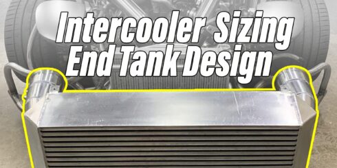
Intercooler Sizing And End Tank Design With Rob Dahm
Rob Dahm rethinks, redesigns, and retests his current intercooler and end tanks to unlock more horsepower on his 4 rotor RX7. Using CFD analysis, he identifies where the current setup has restrictions that are causing pressure drop and robbing Rob’s 4 Rotor of horsepower

2013 – 2018 Ford Focus ST Performance Intercooler
Replace Heat With Horsepower PowerMax performance products by Garrett Motion are vehicle specific turbo and intercooler upgrades for the most popular OEM turbocharged…

Garrett Performance Intercooler Test: 2016+ Honda Civic Si
MotoIQ tests the new Garrett drop-in performance intercooler for the 2016+ Honda Civic Si. 17HP and 14 lb-ft of torque gained over stock when tested in a wind tunnel dyno, all from a drop-in unit.
Making Power With The PowerMax Twin Turbo and Intercooler Upgrade For 3.5L F-150
PowerMax Performance For Your Ford F-150 If you are looking for a little extra power for your ecoboost engine, Garrett PowerMax turbos and intercoolers are…
Performance Intercoolers
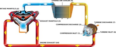
Garrett performance intercoolers and intercooler cores work together with the turbocharger as part of the total induction system. When air is compressed in the turbocharger it gains a lot of heat. Hot air is less dense and therefore is not able to produce as much energy because less can be fed into the engines cylinders. The job of the intercooler is to remove heat from the charge air making it more dense. The denser charge equals more air and fuel reaching the engine and that translates to more horsepower.
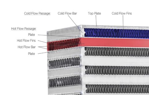
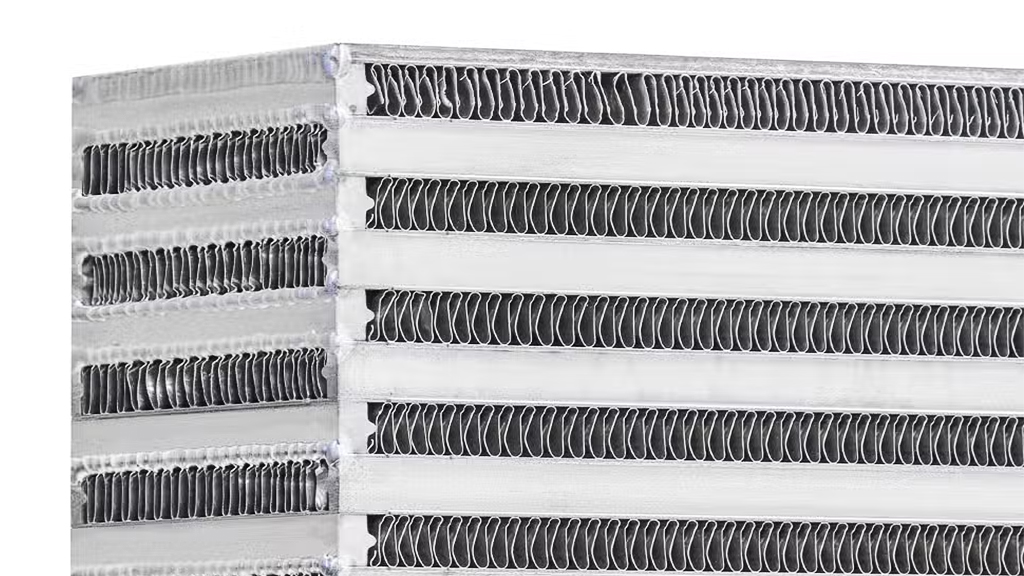
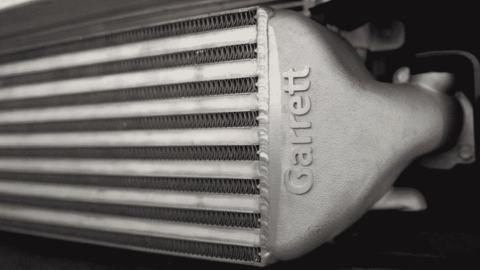
Intercooler Construction
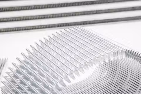
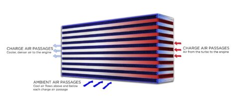
Garrett intercooler cores are bar and plate horizontal flow design. Charge air from the turbo flows within enclosed passages in one direction, with separate cooling passages flowing cooler ambient air in a perpendicular cross-flow pattern to the charge air. In bar and plate designs the passages consist of plates on top and bottom with fins in between. The passages are enclosed by bars on either side depending on if it is a charge air passage or an ambient air/cooling passage. Passages are stacked alternately until the desired stack height is reached. On the sides of the stacked cores, added to the final passage is a side plate of thicker material to provide structural integrity, protect the more delicate fins, and provide a surface for welding on end tanks if desired.
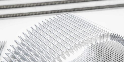
Heat Transfer
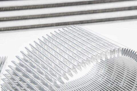
How does the intercooler remove heat from the charge air? There are three types of heat transfer modes, but the bar and plate intercooler relies on Conduction and Convection to extract heat from the charge air. Conduction is the transfer of heat to materials that have direct contact with each other. Convection is the transfer of heat from one place to another by movement of air. As you can see in the image below, the bars, plates, and fins alternate direction and flow and all play a part in extracting heat from the charge air. The charge air fins transfer heat from the charge air to the plates and the ambient air fins transfer the the heat from the plates and the ambient air cools the fins. The process repeats as long the car is moving or until the core gets heat soaked.
Fin Density
Fin density is measured in FPI or fins per inch. Each fin surface counts as one fin meaning there are two fins per wave. Fin stacks start off as flat sheets of aluminum that are fed through a special machine where they are bent to the desired FPI per row height and length. Garrett manufacturers around 20 different air-to-air and air-to-liquid intercooler cores supporting a range of horsepower from 310 up to 1260. Each of those cores are different in length, width, and height to meet the needs of different performance enthusiasts.
Garrett Intercooler cores utilize a combination of fin density depending on the flow path of the core. For example, the cold flow path or the front of the intercooler commonly has a higher density fin count to allow for better thermal performance and cooling. Core width/ cold flow can range from 3 – 5 inches so higher fin density is critical with the short span the ambient air travels across to cool the charge air passages. Additionally, the cold air passages are not sealed or pressurized like the charge air passages, so your ambient air flows through, cools the hot passages and evacuates into the engine compartment.
Hot flow passages have a longer run spanning from 11-28 inches in some intercooler cores. The hot flow path is a series of sealed chambers with fins spanning the entire length. There is a lot of surface area for heat transfer to take place and for that reason, the hot chambers have a lower fin density. This also helps reduce pressure drop as the charge air travels from one side to the other.
Pressure Drop
Pressure drop is the difference in pressure between two points caused by flow resistance. An example of pressure drop is when the air pressure leaving the intercooler is less than the pressure that went in. You may never actually see this happening because your turbo will work harder (spin faster) to deliver the correct PSI to the engine. The faster a turbo spins the hotter the air is so it’s critical to use an intercooler that has a good balance of fin density so you don’t overwork the turbo.
Think about driving down the road with your hand out of the window and your palm facing forward. Your hand is interrupting the flow of the air and it must find a way around your hand to pass. Now imagine you and 10 friends in a limousine with your hands out of the window one after another. The last person in line will not feel the same flow as the first person because of pressure drop.